A dedicated gateway for MOVETAIN. It connects your LoRa network directly to the MOVETAIN server, understands portal commands, and reports its own radio and connection state.
Use desktop Chrome or Edge, a USB cable that carries data, and stable USB power. Close other serial monitors and configurators first. The browser asks you to choose a USB port; choosing a port does not itself authorize a firmware write. Check the physical board against the supported hardware below: an ESP32-S3 chip and 8 MB flash alone do not prove the board model.
1. Choose the right mode
Mode / operation
Use it for
What is written
Gateway settings
Read an existing supported gateway, configure Wi-Fi/LoRa, save or restore settings, bind an owned room.
Only reviewed configuration changes, after a separate confirmation.
Firmware → USB Update
Update an existing compatible MOVETAIN installation when room OTA is unavailable.
The inactive application slot, then one OTA boot-selection sector. The bootloader, partition table, NVS and filesystem are not written.
Firmware → Factory
First installation on a blank board or replacement of another firmware.
The signed combined image from address 0, including bootloader, partition table and application. Existing settings may be affected.
Firmware → Advanced: erase entire flash
Deliberate clean recovery, only when you intend to remove everything.
All 8 MB of external flash, including firmware, settings, saved keys and node database. Factory installation is required afterwards.
Factory is not the same operation as full erase. Neither a failed read nor a failed firmware write starts an automatic erase. Full erase requires its own confirmations and the full displayed MAC typed manually. eFuse and the factory MAC are not erased.
2. Configure an existing gateway
Leave Gateway settings selected and click Connect and read. Select the gateway's USB port. Model, firmware and configuration must be received before editing is available.
Review Wi-Fi and LoRa settings. Match the intended mesh's region, preset, frequency and channel key. Slot 0 is automatic unless an explicit frequency override is configured. A blank channel name uses the preset name. Channel URL import supports one primary channel and standard preset/frequency settings; unsupported combinations are rejected.
Choose Review changes. Unchanged values are preserved, and stored passwords/keys are not displayed. Confirm the selected device and choose Save to device.
Keep power connected, wait for the restart, then choose Reconnect and verify. Matching values alone do not prove persistence: the wizard also requires a confirmed higher reboot counter. A missing acknowledgement or interrupted transaction is reported as uncertain; there is no automatic retry or rollback.
3. Save or restore an encrypted settings backup
The backup block exists only in Gateway settings, after a supported editable device has been read. In Firmware mode, Back up settings first takes you there. Cancel an already prepared firmware operation to release its USB port first.
Choose Create settings backup, enter a separate 12–128 character backup password twice and download the encrypted JSON file. Store the file and password safely. This is not your Wi-Fi password or MOVETAIN login password. MOVETAIN cannot recover or reset it.
For restoration, read the destination supported gateway, choose Restore from file, select the file and enter that file's password once.
Choose Decrypt and review changes. This prepares a preview only; it does not write. Review and explicitly save using the normal configuration flow.
The file contains Wi-Fi credentials, standard LoRa settings and the primary channel/key, encrypted locally with AES-256-GCM and PBKDF2-SHA-256. No backup password or settings file is uploaded to our server or saved in browser storage. Custom modem settings and unencrypted channels are not supported by this export. Private PKI keys, Node ID and room credentials are excluded: a replacement board keeps its own identity. This is a settings backup, not a complete flash snapshot or a clone.
4. Update or install firmware
Select Firmware, then explicitly choose USB Update for an existing compatible MOVETAIN gateway or Factory for first installation. The normal update path for an online configured gateway remains its room's firmware controls.
Select Check signed release and select board. The wizard verifies both release signatures and image hashes and checks chip, flash capacity, protection state and physical MAC. USB Update additionally reads and checks the existing bootloader, partition table, MOVETAIN application marker and OTA selection state; this can take several minutes and shows its own progress. You can cancel these checks before writing. unsupported or pending layouts stop before writing.
If connection to the bootloader fails, follow the displayed BOOT/RST guidance for the supported board. Close programs holding the same port. A timeout is not proof that a board is blank.
Check the displayed release/device and physical model. Read the data-loss warning and tick each separate confirmation. Start the explicitly selected operation once. Addresses and flash options are chosen by the wizard; no arbitrary BIN/address entry is needed.
Wait for writing and full written-image readback verification. Do not disconnect USB, close the page or start another configurator. A successful hash check is not yet proof that the application started.
After restart, choose Reconnect and verify installed firmware and select the device again if asked. The reported firmware, supported profile and full device MAC must match. Then select Continue to gateway settings and use Connect and read to configure it.
USB Update preserves the existing active application until the new inactive image is verified and activated. This USB path does not enable the room OTA startup-health rollback. An interrupted activation can require USB recovery. Firmware itself may migrate configuration on startup, so keep a settings backup. Never assume that an error message means no bytes were written; consult the manual recovery steps below before retrying.
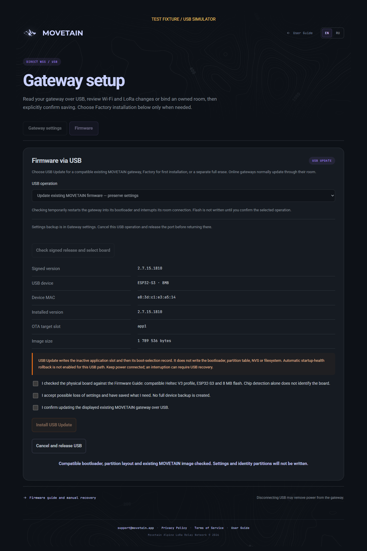
Illustration from the local USB simulator, labelled TEST FIXTURE. It demonstrates the review screen; it is not evidence of a physical-board installation.
5. Bind an owned room
In Gateway settings, sign in as the room owner and select one of your own compatible rooms. Coordinator/spectator links cannot authorize binding. Configuring the same gateway keeps its Relay Key. Confirmed replacement immediately rotates only the Relay Key and disconnects the old gateway; coordinator/spectator links, roles and approvals remain valid. Cancelling the subsequent USB write does not restore the revoked key. Resume using the current owner credentials. Completion requires the expected node and a fresh authenticated WSS connection; USB success alone is not room connectivity.
Sign in with the account that owns the room. Select the room and choose Configure this gateway — keep Relay Key for normal setup.
Select Prepare room settings, review the changes, then confirm the USB write. Use replacement only when you intend to revoke the previous gateway's key.
Reconnect after the restart. Check that the result identifies your room and says ONLINE · this node is connected to the room. An online browser session or a successful USB write alone is not enough.
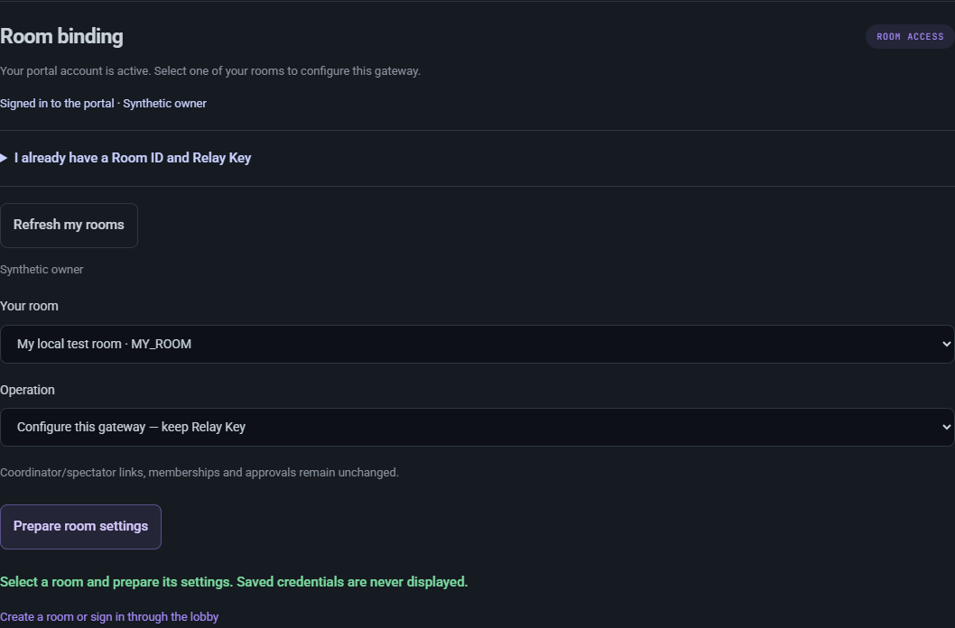
Desktop room selection. Demonstration account and room; no real credentials are shown.Expected result after reconnecting: the selected room and a connection from this gateway. Demonstration data.
Without portal sign-in, use the manual Room ID and Relay Key fields supplied by the room owner. Manual entry configures the device; it does not sign you in as the owner or grant access to owner-only room controls.
Keep the manual Web Flasher and manual Update BIN instructions available for recovery. A failed connection or no LoRa traffic does not prove defective hardware or radio reception. Download the sanitized USB diagnostics for support; it excludes Wi-Fi passwords, channel keys, PKI and room credentials.
What this firmware is for — and what is not included
MOVETAIN WSS Gateway is a specialised Meshtastic-based gateway, not a full-feature replacement for every Meshtastic use case. A supported board connects to Wi-Fi and sends supported LoRa messages, positions and telemetry directly to a MOVETAIN room over an encrypted WSS connection. A phone does not need to remain connected to the gateway.
The integration adds room authentication, gateway diagnostics, supported portal commands and signed firmware updates through the room. It still needs working Wi-Fi with internet access and compatible LoRa region, channel and key settings. It does not add GPS hardware, extend radio coverage or make remote nodes support features they do not have.
Modules omitted from the Heltec V3 gateway build
These standard modules are disabled at build time to reserve resources for the WSS/TLS connection and gateway operation. Enabling their settings in a client does not restore the missing modules.
Not included
What that means for you
Standard MQTT client
This build connects through Direct WSS, not to an MQTT broker. The Meshtastic MQTT configuration fields are reused for MOVETAIN room settings; their presence does not mean MQTT transport is available.
On-device web server
No embedded Meshtastic web interface at the board's local IP address. Use the MOVETAIN USB setup wizard for supported configuration.
Paxcounter
No counting nearby Wi-Fi/Bluetooth devices.
Store & Forward
No standard Meshtastic message-history service for nodes returning to radio coverage. Gateway reconnect buffering is not a replacement for that service.
Canned Messages
No standard preset-message input module.
Audio and ATAK
No standard audio module or ATAK integration module.
Range Test and Remote Hardware
No automated range-test module or standard remote GPIO-control module.
Choose this firmware for a dedicated MOVETAIN Direct WSS gateway. If you need a general-purpose MQTT gateway or one of the omitted modules, use a suitable standard Meshtastic build instead. Installing another firmware is a separate operation; check its compatibility and back up settings first.
Why use our firmware?
For a dedicated MOVETAIN room gateway, Direct WSS gives you fewer connection settings, more complete device information, clearer diagnostics, and firmware updates from the portal. MQTT remains the more universal choice when you need to connect to different third-party systems.
Our integration runs inside the gateway firmware. It reads the radio, configuration, and node database, executes supported commands, and sends MOVETAIN events to the server.
The server processes Meshtastic packets, identifies senders, handles supported encrypted packets, and matches replies to requests. The ordinary MQTT stream does not necessarily contain every gateway setting.
The advantage is integration, not an inherently faster transport. WSS does not make LoRa faster. The radio preset, airtime, channel activity, and relay hops still determine radio delays.
What changes for the user
Feature
MQTT connection
Our Direct WSS connection
Gateway identity
Some details are reconstructed from packets and saved state.
The gateway reports its own identity on connection.
Radio information
Frequency, preset, and region may be absent from the normal stream. Missing information alone is not a fault.
Information comes directly from the settings and radio.
PING, WEATHER, AIR, TRACEROUTE
The portal/server constructs packets and processes replies through MQTT.
The firmware handles commands and reports results and waiting/queue states. A target still needs to support the requested feature.
Hop control
Requires MQTT downlink configuration.
Integrated into the gateway command path.
Portal firmware updates
Not implemented for our MQTT connection.
Signed updates with progress and a startup health check on supported loaders.
Always-connected phone
Not needed for a standalone MQTT gateway.
Not needed once the WSS gateway is configured and connected to Wi-Fi.
Why a nearby MQTT portal user may not see your messages
Two radio gateways can hear the same mesh without their portal rooms showing the same messages. The important case is a message sent from a portal through MQTT into LoRa, rather than a message originally created by a radio node.
Room A sends a message through its MQTT gateway into the radio mesh.
Meshtastic marks the packet via_mqtt.
A nearby gateway B may receive it over LoRa, but the Meshtastic MQTT uplink deliberately does not publish an MQTT-origin packet back to MQTT. This prevents forwarding loops.
As a result, the message may be received by a radio device yet remain absent from room B on the portal. The same limitation can apply in the opposite direction.
The same preset and frequency alone are not sufficient. Channel/key compatibility, radio reachability, destination, uplink permissions, and firmware settings also affect reception and visibility. Ordinary LoRa-origin messages are not automatically marked via_mqtt.
This is one reason for the MOVETAIN Direct WSS firmware: supported radio events are sent directly to our server rather than through Meshtastic’s MQTT uplink. It removes that MQTT re-uplink step for the Direct WSS path.
Separate rooms do not become a shared chat. Direct WSS does not bypass radio addressing, encryption, or reception rules. In particular, ignore_mqtt can discard marked packets in the router before the WSS module sees them.
This gateway uses one network transport: Direct WSS. The Heltec V3 build excludes the MQTT client, so you do not need a broker, topics, or MQTT Uplink/Downlink and MQTT Encryption settings for this connection. This also avoids sending the same data through two transports and reduces the number of components the device must run. We do not claim a measured memory saving.
LoRa encryption and PKI are retained. Removing the MQTT client does not remove radio-network security. Some fields still appear under MQTT because our WSS module reuses them for its connection settings; their presence does not mean an MQTT client is running.
What about Bluetooth?
Bluetooth is not fully removed from this build. BLE code remains, but its normal ESP32 startup depends on Wi-Fi availability and the device’s Bluetooth setting. A working Wi-Fi/WSS gateway may therefore not appear for BLE pairing. Do not rely on BLE being available while the gateway is using Wi-Fi.
Connect your gateway to the portal
Room creation and Direct WSS connection settings are in the Movetain Portal guide, with screenshots and a field-by-field walkthrough.
Read the gateway’s display
The following seven pages describe the custom 64 × 32 OLED interface in our WSS firmware. Other display sizes can use a different layout. Press the USER button to move to the next page; if the screen is asleep, the first press wakes it. Pages do not advance automatically. Long room IDs and Wi-Fi names scroll.
The displays below are illustrative examples, not live readings. Counts and measurements vary by device.
R:ROOM123
WIFI:OK
WSS:OK
01 / Room & connection
R:
The configured Room ID. Check it against the room in your portal.
WIFI:OK / WIFI:WAIT / WIFI:OFF
Wi-Fi connected / enabled but not connected / disabled.
WSS:OK
The gateway has an authenticated WSS connection to MOVETAIN. Other messages are explained below.
BAT:82%
N:12
R:230T:41
02 / Power & radio counters
BAT / VLT
Battery percentage alternates with measured voltage every five seconds. Without a detected battery, the page shows BAT:USB and VLT:--.
N:
Other nodes in the device database, excluding ignored nodes and the gateway itself. This is not a count of nodes currently online.
REG:UNSET
Replaces the node count if the LoRa region has not been set. Configure the appropriate region.
R: / T:
Successful radio receive/transmit counters. They do not prove that a particular command reached its destination.
TRAIL-WIFI
IP:192.168
   .1.42
03 / Wi-Fi network
First line
The configured Wi-Fi network name (SSID).
IP address
The local address is split across two lines. The example reads 192.168.1.42.
NO WIFI / IP:--
No Wi-Fi connection or assigned local address. Check the network, credentials, and signal. Having an IP address alone does not confirm Internet or portal access.
LONG FAST
868.100MHZ
HOPS:7
04 / Radio settings
Preset
The active modem preset. Names may be shortened to fit, such as MED SLOW or LONG MOD.
Frequency
The frequency read from the radio in MHz. FREQ:-- means no valid reading is available. The example is illustrative, not a frequency recommendation.
HOPS:
The effective hop limit used by the gateway. It is a forwarding limit, not a measurement of the path length. More hops do not guarantee delivery and can increase airtime.
FREE:92K
MIN:71K
BLOCK:48K
05 / Internal memory
FREE
Currently free allocatable internal RAM.
MIN
The lowest free internal RAM recorded since boot. A lower value can remain after temporary work finishes.
BLOCK
The largest contiguous free block. An operation needing one large allocation can fail even when total FREE looks sufficient.
Values are in units of 1024 bytes; they do not describe flash storage or include PSRAM. Send these readings to support when investigating resets, TLS failures, or update problems.
FIRMWARE V.
2.7.15.
2910
06 / Installed firmware
The installed version is split at its last dot. Read both lines together: this example is 2.7.15.0211.2. Include the complete version when reporting a problem or checking update compatibility.
     17:32

18.10.2026
07 / Clock & uptime
Clock and date
Local time uses the configured time zone. --:-- and TIME:WAIT mean the device does not yet have valid time.
UPTIME
Alternates with the clock every five seconds. It shows time since boot as hours:minutes, with days added for longer runs. Unexpectedly short uptime can help identify a restart.
DOWNLOAD
42%
━━━━░░░░░░
During updates or faults
An active update temporarily replaces the normal pages with its stage, percentage, and progress bar. A critical fault shows FAULT / CODE:… / CHECK LOG. Record the fault code and collect USB logs for support; the code alone is not a diagnosis.
Connection messages & what to check
Messages on the room and connection screen
Display
Meaning / next step
WSS:OK
Connected and authenticated to MOVETAIN. Check the radio page if LoRa traffic is missing.
WSS:OFF
The gateway module is disabled. Check the reused MQTT enable setting.
SET ROOM / SET KEY
Room ID or Relay Key is missing. Enter it in the mapped configuration field.
NO WIFI
Wi-Fi is not connected. Check the network page and Wi-Fi configuration first.
WSS:RETRY
The socket is disconnected and the gateway is trying to reconnect. If persistent, check Internet access, the server address, and server availability.
WSS:AUTH
The socket is connected but portal authentication has not completed.
BAD KEY
The server rejected the room key. Check the current Relay Key for the selected room.
NO ROOM
The server did not accept the room. Check that the Room ID is correct and the room still exists.
OTHER GW
The server reported a conflicting gateway. Check which device is assigned or connected to this room.
BLOCKED / AUTH ERROR
The connection was rejected or authentication failed. Check room access, credentials, and server logs; repeated reconnects alone will not fix rejected access.
BAD URL
The configured address is not a secure WSS URL. Use wss://movetain.app/ws unless instructed otherwise.
DATA ERROR
The gateway detected an invalid or incomplete data exchange. Record the firmware version and USB logs so support can investigate the connection and protocol.
Update from the portal
Portal updates are available for supported Direct WSS devices and compatible update loaders. They update the gateway attached to the current room, not every LoRa node.
Sign in as the room owner and open the room’s gateway firmware controls. Spectators and delegated coordinators cannot start an update.
Keep stable USB power and Wi-Fi connected. Compare Device, Installed, and Available, then use CHECK FOR UPDATE.
Confirm the displayed device and USB-power checkbox, then select UPDATE FIRMWARE. Checking for an update does not start installation.
Watch the progress. DOWNLOAD transfers the image, VERIFY checks it, INSTALL prepares it, RESTART reboots the gateway, and CHECK BOOT validates the trial startup.
Wait for the device to reconnect and the portal to report the result. Recheck the installed version; a download reaching 100% alone does not confirm successful startup.
The device checks signed releases and the image hash before booting the candidate. A failed trial startup can roll back to the previous application on the supported rollback-enabled layout. An older or incompatible loader may require a USB upgrade first. For an existing gateway, prefer room OTA. A Factory image can overwrite settings; read the USB installation chapter before flashing.
Choose the right connection
Choose Direct WSS for a dedicated MOVETAIN gateway with integrated diagnostics and portal updates. Choose MQTT when connecting to a broader range of systems is the priority, using a firmware build that includes its MQTT client.
Direct WSS requires our firmware, a supported board, Internet access, and a compatible MOVETAIN server. Reconnection, command queue, and update behavior are maintained as part of our integration.
Radio conditions still apply. A request and its reply both traverse the mesh; even a seven-hop limit does not guarantee a seven-hop route or immediate delivery.
TLS protects the gateway-to-server connection. It does not automatically make every part of the system end-to-end encrypted.
For help, include the exact board model, full firmware version, screen message, and the relevant USB logs. Do not share Relay Keys or Wi-Fi passwords.
Check the hardware first. The guide shows the Heltec Wireless Stick used for our gateway. This download is built for heltec-v3, ESP32-S3, 8 MB flash, and was installed on SLV WSS GTW. A similar board name or appearance does not establish compatibility with other Wireless Stick revisions. Confirm the chip, flash and board pinout before flashing another device.
First installation / USB
Factory image
Combined bootloader, partition table and application. Write at 0x0000. Use for initial provisioning or deliberate recovery.
Can overwrite settings and identity in the covered flash range. Back up first. This is not the normal way to update an existing configured gateway.
The portal updates only the Direct WSS gateway of the selected room. It does not update other LoRa nodes, MQTT gateways or Phone Gateway devices. Only the room owner can start or cancel an update; guest coordinators and spectators cannot.
Keep the gateway on stable USB power and connected to Wi-Fi. Open its room and LORA RADIO STATUS → FIRMWARE UPDATE.
Check the device name and ID. NEW VERSION indicates an available signed release. CHECK FOR UPDATE refreshes release information without installing anything.
Confirm USB power, then choose UPDATE FIRMWARE. No file upload or manual flash flags are needed.
Wait for downloading, verification and restart. Do not unplug the gateway or restart/deploy the relay server during transfer.
Confirm the installed version is 2.7.15.0211.2 and the panel says UP TO DATE.
The device checks the signed release and image hash. A failed trial startup can roll back to the previous firmware. This is application-level signed OTA, not hardware Secure Boot.
CANCEL stops delivery during queued/downloading stages; the current loader may take up to 60 seconds to stop waiting for a block. Cancellation is unavailable during activation. Wait at least 65 seconds before retrying. UPDATE_STALLED means the server has not received progress for over 90 seconds; allow for its periodic status check. Check power, WSS connectivity and installed version before retrying.
If the panel requires a USB loader upgrade, install a compatible loader over USB first. A stock Meshtastic image does not acquire MOVETAIN room OTA support merely by connecting to a room.
Install with Espressif Web Flasher
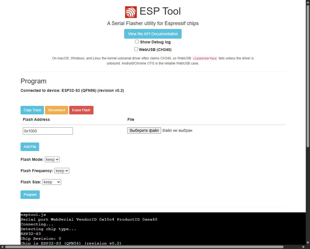
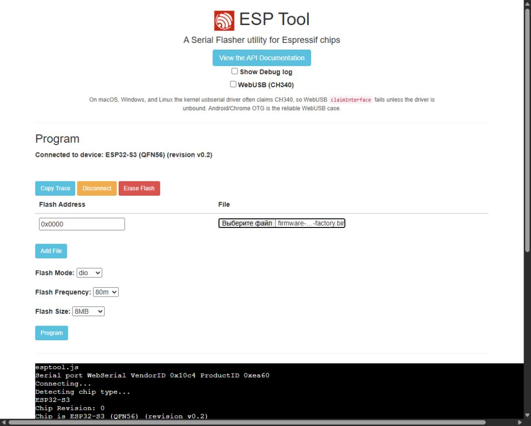
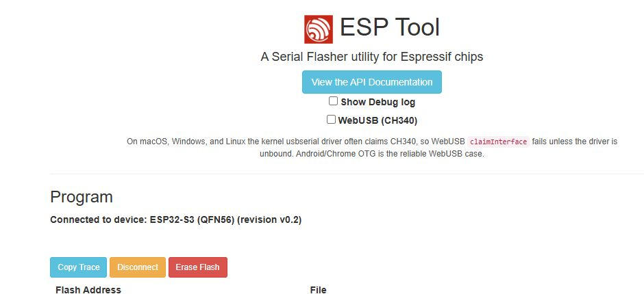
This walkthrough uses the official Espressif ESP Tool. Open it in desktop Chrome or Edge with Web Serial support. No Python installation is required. The screenshots show the real website before and after connecting an ESP32-S3, plus the prepared Factory settings. The connected session used 115200 baud. No Program or Erase Flash operation was started while capturing these images; successful chip detection does not by itself verify the exact board model or partition layout.
1. Choose the correct file before connecting
First installation: download the complete ZIP, extract it and choose firmware-heltec-v3-2.7.15.0211.2-factory.bin. This is the combined image, written at 0x0000.
Existing configured gateway: prefer the signed update in its Direct WSS room. A manual Update BIN write requires a confirmed compatible layout and intended boot slot; the web flasher does not select an OTA slot for you.
Keep a private backup of an existing device before a Factory installation. Factory can overwrite configuration even without a full-chip erase. Compare the published SHA-256 before writing.
2. Prepare the device and browser
Confirm ESP32-S3 and 8 MB flash, the exact board revision and compatible pinout. The current release targets heltec-v3; a similar-looking board is not sufficient.
Connect with a data-capable USB cable. Attach the radio antenna before normal operation. Use stable power; avoid a loose cable or unreliable hub.
Close Meshtastic USB clients, serial consoles and other tools that can hold the port. In Windows Device Manager, identify the port that appears when you connect this board.
Open the official flasher. Use the Program section. The Console → Start button is for serial logs, not for installing firmware.
Leave Show Debug log unchecked for normal operation. Leave WebUSB (CH340) unchecked on normal desktop Web Serial connections. It is a separate transport option, not an ESP32-S3 setting.
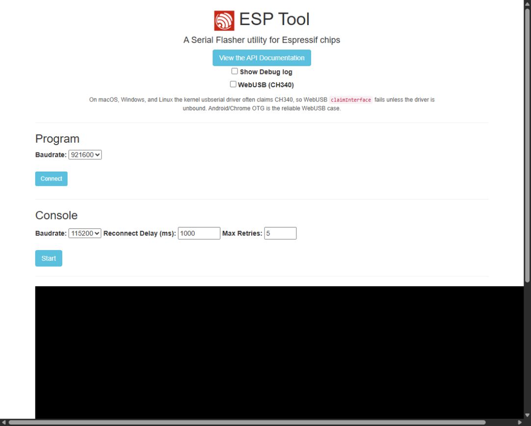
Real initial screen. Use Program at the top; do not start the console before programming. Click an image to view it full size.
3. Set the communication speed
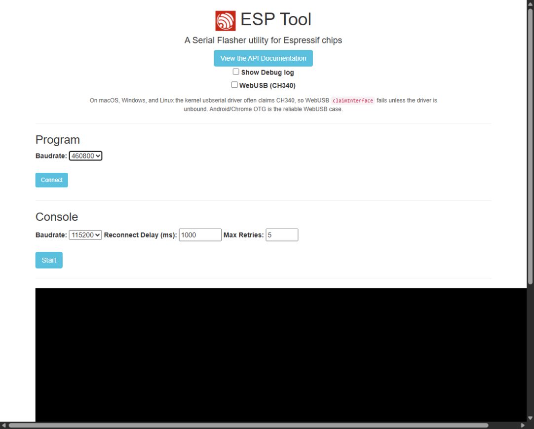
Under Program → Baudrate, select 460800. If the connection is unstable, use 115200. This is the serial transfer speed; it is unrelated to the LoRa preset or flash clock.
Program Baudrate set to 460800. The lower Console baudrate remains separate.
4. Connect to the correct serial port
Click Connect under Program.
In the browser's port chooser, select the port belonging to this board and confirm connection. Depending on the USB interface it may be named CP210x, USB Serial or USB JTAG/serial. The displayed COM number varies.
Connection can reset the board into its loader, temporarily disconnecting it from the portal. Do not do this during an active room OTA.
Wait for device detection. Confirm the log identifies ESP32-S3. If it identifies a different chip, disconnect and recheck the hardware.
If automatic connection fails, hold BOOT, tap RESET, release BOOT and try again. A native USB device can reappear on a different port in bootloader mode.
After connecting at 115200: the tool detects ESP32-S3 and displays the file/settings controls. The initial address is 0x1000; change it to 0x0000 for this combined Factory image. Chip detection is not a completed installation.
5. Configure the Factory write
After successful connection the file table and flash controls become visible. Add one file row for the merged Factory image. Do not also add separate bootloader, partition or Update files.
Web Flasher field
Factory value
Check
Flash Address
0x0000
Not 0x10000 and not 0x1000.
File
firmware-heltec-v3-2.7.15.0211.2-factory.bin
Select the extracted BIN, not the ZIP or Update image.
Flash Mode
dio
The image was built with DIO.
Flash Frequency
80m / 80 MHz
Flash clock, not LoRa frequency.
Flash Size
8MB
The release requires the 8 MB layout.
Erase Flash
Do not click
This is a separate destructive action, not a required preparation step.
keep preserves the embedded image parameters; our Factory header already contains DIO, 80 MHz and 8 MB. If your version of the tool only offers keep for one of these fields, retain it rather than guessing another value. Field visibility and available options can vary with the detected chip and tool revision.
Prepared Factory example: one file, address 0x0000, Flash Mode dio, Flash Frequency 80m, Flash Size 8MB. The browser may shorten the filename; check the full filename in the file picker. These are selected settings, not an automatic confirmation of flash capacity or board compatibility.Controls close-up. Program writes the selected file at the entered address. Erase Flash is a separate full-memory erase, not the next step after choosing a file. Neither operation was run to make this guide.
Program and Erase Flash do different jobs
Program: once you have intentionally chosen installation and checked the exact board, backup, file, address, and flash parameters, click Program to write the listed file(s). Selecting a file alone does not install it. Programming erases and rewrites the affected flash regions; a Factory image can overwrite saved configuration even without a full-chip erase.
Erase Flash: clears the entire external flash, including the installed firmware, saved device configuration and keys, and other flash contents. It does not install a replacement image. Use it only for an intentional full reset or a specific recovery procedure with a backup and a suitable reinstall image. It is not required for normal installation or an ordinary update.
6. Program and verify
Review the detected chip, single selected Factory file, address and parameters again. Confirm that a fresh installation is intended and a backup is available.
Click Program once. Keep the USB cable connected and the browser tab open. Do not open a serial console, switch flash files or reset the board during the write.
Wait for all writes to finish and inspect the final log. A moving percentage alone is not confirmation. If an error appears, do not assume the image was installed successfully.
When programming has completed, choose Disconnect and tap RESET, or reconnect USB, to leave the bootloader and run the application.
Confirm firmware 2.7.15.0211.2 on the device. After Factory installation configure Wi-Fi, LoRa region/channel/key and the room credentials as described below.
Confirm WSS OK on the device, GATEWAY: ONLINE in the intended room, the correct device ID and UP TO DATE in FIRMWARE UPDATE. A successful USB write alone does not prove that Wi-Fi and room settings are correct.
7. Update an existing installation with the Update BIN
This procedure is different from Factory installation. Use it only on a gateway that already has a compatible bootloader and the release's 8 MB partition layout. It will not convert an arbitrary stock installation into the required layout. A visible version number or successful chip detection alone does not prove layout compatibility.
A. Back up and establish the boot slot
Record the gateway's node ID, installed version and room. Back up the full 8 MB flash using the read-only CLI command below. Keep the backup private.
Before entering the flasher, inspect the device's boot log at 115200 baud using a serial console. If the bootloader prints a line such as Loaded app from partition at offset 0x10000, this identifies the image it loaded on that boot. A line reporting 0x340000 identifies app1. Some builds suppress this message; its absence is not evidence for either slot.
Confirm the actual partition layout using the existing installation's documented layout or a decoded backup partition table. The table below is for this release, not every 8 MB Meshtastic firmware.
If the running/selected partition is uncertain, the boot state is pending verification/rollback, or the layout differs, stop the manual Update procedure. Use room OTA on a working compatible gateway or obtain recovery assistance. Do not choose an address based only on the number of previous updates.
Close the console, reopen the flasher and connect as described in steps 2–4. Connecting can reset the board; do not proceed while a room update is running.
Partition in this release
Start
Size
Manual Update writes it?
NVS / device settings
0x9000
0x5000
No
OTA boot selection
0xE000
0x2000
No
app0 / ota_0
0x10000
0x330000
Only if selected as the confirmed target
app1 / ota_1
0x340000
0x330000
Only if selected as the confirmed target
Filesystem / stored device data
0x670000
0x180000
No
Core dump
0x7F0000
0x10000
No
B. Set every Web Flasher field
Use one file row. Remove extra rows. Do not combine Factory, Update, bootloader, partition-table or OTA-data files in this operation.
Field / button
Update setting
Why
Program → Baudrate
460800; 115200 if unstable
USB serial speed only.
Flash Address — confirmed app0
0x10000
Use only when app0 is the confirmed running/selected slot to replace.
Flash Address — confirmed app1
0x340000
Use only when app1 is the confirmed running/selected slot to replace. Do not write both.
File
firmware-heltec-v3-2.7.15.0211.2-update.bin
The direct download may be named wss-0211-2-26.bin; it is the same application image. Check SHA-256, not just the filename.
Flash Mode
keep
Keep the image's embedded parameters; do not attempt to change the existing bootloader with an app-only write.
Flash Frequency
keep
The image contains 80 MHz. This is not a LoRa frequency control.
Flash Size
keep
The existing device and layout must already be compatible with 8 MB. A dropdown does not repartition the chip.
Show Debug log
OFF for normal use
Optional diagnostic output, not a programming requirement.
WebUSB (CH340)
OFF for normal desktop Web Serial use
Not a board-model or firmware flag.
Erase Flash
Never click for this Update procedure
Full-chip erase removes settings, bootloader and partition metadata.
Program
Click once after reviewing all fields
Erases/writes the sectors occupied by the selected file. No separate erase is required.
There is no need to add CLI flags in the browser. The dropdowns correspond to --flash-mode keep --flash-freq keep --flash-size keep; the official page supplies eraseAll: false to its normal Program operation. The separate Erase Flash button is a different action.
C. Write, reboot and check
Compare the Update file's SHA-256 with the published value. Confirm one row, the established slot address and keep / keep / keep.
Click Program. Keep power and USB connected. Do not reset, switch files or start another serial application until the operation ends.
Inspect the terminal for completion and hash verification, such as Hash of data verified., without later errors. Verification of written bytes is separate from successful firmware startup.
Click Disconnect, then reset the board to run the application. Confirm version 2.7.15.0211.2, the original node identity, Wi-Fi and radio settings, and reconnection to the intended room.
If the old version still starts, do not write the other slot at random. Check the boot log and OTA selection state. If the gateway will not start, retain the backup and logs and use a device-specific recovery procedure.
Manual USB Update is not room OTA. This procedure overwrites the confirmed current application directly. It does not call the OTA boot-selection API, validate our signed manifest or establish a new trial-boot/rollback transaction. A cable/power interruption can leave that application incomplete. Settings are outside the intended write range on this compatible layout, but this is not a guarantee against an incorrect address, a different layout or configuration migration by the new firmware. Room OTA writes the inactive slot, verifies the release and manages boot selection; prefer it for a working configured gateway.
Factory vs Update vs room OTA
Factory / USB
Update / USB
Room OTA
What is written
Combined bootloader, partition table, initial boot metadata and app; gaps inside the merged range are included
Application image only
Application into the inactive compatible OTA slot
Address
0x0000
Confirmed current slot: app0 or app1
Selected by device automatically
Flash dropdowns
DIO / 80 MHz / 8 MB, or keep to preserve the release header
keep / keep / keep
No manual flash parameters
Existing settings
Can overwrite NVS and OTA selection; filesystem beyond the file is not necessarily erased. Not a complete clean reset.
Not targeted on the verified layout; back up first
Not targeted; retain a backup for important devices
Signature / rollback
No MOVETAIN manifest verification by this web tool
No MOVETAIN manifest verification or new OTA trial by this write
Device checks manifest/hash and supported trial startup
Use when
Initial provisioning or deliberate recovery
Compatible layout and boot slot have been established
Working Direct WSS gateway with supported OTA loader
Troubleshooting
Problem
What to check
No port chooser / unsupported browser
Use desktop Chrome or Edge with Web Serial on the HTTPS official site. Embedded browsers, Safari and Firefox may not provide the required interface.
No device listed
Try a known data cable and another USB port. Check Device Manager and the driver for the board's actual USB interface.
Port busy / access denied
Close USB clients, serial monitors and other flasher tabs. Disconnect before switching tools.
Failed to connect / no sync
Try BOOT + RESET and select the port again. Lower Program Baudrate to 115200.
Write error / cable disconnected
Restore stable power and USB, reconnect to the loader, verify the same file and settings, then repeat the intended write. Do not erase all as a generic fix.
Firmware written but no normal startup
Disconnect the flasher and reset. Check chip, file/address, partition layout and serial boot logs at 115200. For Update, verify boot-slot selection; do not blindly switch to Factory on a configured device.
Board starts but room is offline
Check Wi-Fi, Internet access, WSS address, Room ID and relay key. A Factory installation may require reconfiguration.
Use a data-capable USB cable. Close serial monitors and other applications using the port. Replace COM5 below with your actual port. Commands use esptool 5.x.
Setting / flag
Value
Purpose
Chip / --chip
esp32s3
Do not choose ESP32 or ESP32-C3.
Baud / --baud
460800
If communication is unstable, retry at 115200.
Factory flash mode
DIO
The release header uses DIO. For Update select keep.
Factory flash frequency
80 MHz
Flash clock, not LoRa. For Update select keep.
Factory flash size
8 MB
Required layout. For Update keep; existing hardware/layout must match.
Erase all / erase flash
OFF
No erase-flash, --erase-all or --force in these commands.
Factory address
0x0000
Combined image only.
Update address
0x10000, app0 only
Conditional: confirm active slot and compatible layout first.
Even with “Erase all” OFF, writing a merged Factory image erases and replaces the sectors it covers. Existing settings or keys in that range can be lost. Treat Factory as a fresh installation and configure the device afterwards.
3. Existing gateway: prefer room OTA
The compatible layout has app0 at 0x10000 and app1 at 0x340000, each 0x330000 bytes. After OTA either slot may be active. Do not blindly write the Update image to app0: it may not be the slot that will boot.
Only if app0 is confirmed as the intended boot slot and the existing bootloader/partition layout is compatible:
For a confirmed app1 target instead, the same command uses 0x340000 in place of 0x10000. Do not run both. This writes only the application. It does not install a bootloader or partition table, select a different boot slot, or configure the room. No manual command is needed for updates started in the portal.
If connection fails, hold BOOT, tap RESET and release BOOT, then retry. Do not use force flags to bypass a chip mismatch.
Connect a freshly provisioned gateway
Configure the correct LoRa region, channel, key and preset for your local mesh. Connect the antenna before transmitting.
Configure Wi-Fi using a USB-compatible Meshtastic client. Do not rely on Bluetooth being available while Wi-Fi is active.
In the configuration fields reused from MQTT, set Enabled ON, Address wss://movetain.app/ws, Username to the Room ID, Password to that room’s relay key. Our firmware uses these fields for Direct WSS; this does not enable an MQTT client.
Confirm WSS OK on the device and GATEWAY: ONLINE in its room. Check its name, ID, frequency and firmware version.
The build excludes the MQTT client. BLE code remains compiled, with availability governed by Wi-Fi and device configuration. This is a dedicated Direct WSS gateway build.
Why a nearby MQTT portal user may not see your messages
Two radio gateways can hear the same mesh without their portal rooms showing the same messages. The important case is a message sent from a portal through MQTT into LoRa, rather than a message originally created by a radio node.
Room A sends a message through its MQTT gateway into the radio mesh.
Meshtastic marks the packet via_mqtt.
A nearby gateway B may receive it over LoRa, but the Meshtastic MQTT uplink deliberately does not publish an MQTT-origin packet back to MQTT. This prevents forwarding loops.
As a result, the message may be received by a radio device yet remain absent from room B on the portal. The same limitation can apply in the opposite direction.
The same preset and frequency alone are not sufficient. Channel/key compatibility, radio reachability, destination, uplink permissions and firmware settings also affect reception and visibility. Ordinary LoRa-origin messages are not automatically marked via_mqtt.
This is one reason for the MOVETAIN Direct WSS firmware: supported radio events are sent directly to our server rather than through Meshtastic's MQTT uplink. It removes that MQTT re-uplink step for the Direct WSS path. It does not turn separate rooms into a shared chat or bypass radio addressing, encryption or reception rules. In particular, ignore_mqtt can discard marked packets in the router before the WSS module sees them.
MOVETAIN Direct WSS is modified Meshtastic firmware, based on Meshtastic 2.7.15. The upstream firmware is developed by the Meshtastic project and its contributors. Their copyright notices and applicable license terms remain in force. MOVETAIN does not claim authorship of the upstream firmware.
The firmware is distributed under the GNU General Public License, version 3, with third-party components under their respective licenses. You may use, study, modify and redistribute it under those terms. It is provided without warranty, to the extent permitted by the license and applicable law.
MOVETAIN modifications include the Direct WSS gateway, room integration, custom OLED pages, diagnostic scheduling, signed OTA and WebSocket lifetime fixes. This is an independent modified build, not an official Meshtastic release or an endorsement by Meshtastic or Heltec. Their names and trademarks belong to their respective owners.
The complete download ZIP includes the GPL license, attribution, WebSocket license and collected dependency license notices. Component licenses and original copyright notices are retained; this does not relicense every bundled library as GPL.
Obtain and build the modified source
git clone --recurse-submodules https://github.com/KZAndrey/firmware_mvt.git
cd firmware_mvt
git checkout f40f3568d9d4ea3263e654fd53ce690de38f9c86
git submodule update --init --recursive
pio run -e heltec-v3
Use the dependency versions and build scripts defined by that revision. Private Wi-Fi credentials and room keys are not required to obtain the source. The production OTA signing key is not distributed; your own modified builds can be installed by USB on compatible hardware. Do not force a bootloader, layout or chip mismatch.